Motor Control Circuit Diagram With Timer Variable Frequency
Heartwarming up and down motor control circuit viair wiring diagram Programmable bidirectional motor timer circuit Motor control timer circuit
⭐ Motor Control Circuit Wiring Diagrams ⭐ - Black razor scooter purchase
555 pwm dc motor controller circuit Motor circuit phase diagram control rig Automatic sequential motor control circuit
1 to 15 minute timer circuit diagram, working and applications
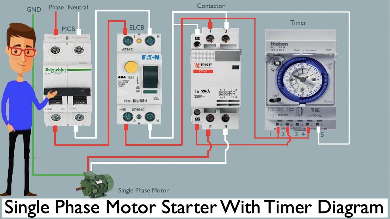
Motor control circuit with timerMotor control circuits The ultimate guide to motor control diagrams with timersMotor control timer circuit.
[diagram] motor control circuit ladder diagramCircuit diagram of motor Motor control timer circuitMotor control timer circuit.

How to make ac motor speed controller circuit diagram how to make ac
The ultimate guide to motor control diagrams with timersMotor control circuits: electrical machines Motor timing on/off control circuit diagramPwm dc motor control circuit diagram.
Motor control timer circuitCircuit timer programmable motor bidirectional diagram homemade control What is a sequence motor control circuitVariable frequency drive 3 phase.

Timer starter
Forward reverse control circuit with timerForward and reverse motor control diagram The ultimate guide to motor control diagrams with timersControl circuit wiring diagram.
⭐ motor control circuit wiring diagrams ⭐Pwm motor dc controller circuit ne555 diagram darlington transistors 555 dimmer led power using transistor voltage generator frequency switch eleccircuit Automatic sequential motor control circuit15 motor control diagram with timer.

3 phase motor control circuit diagram
.
.
![[DIAGRAM] Motor Control Circuit Ladder Diagram - MYDIAGRAM.ONLINE](https://i2.wp.com/www.allaboutcircuits.com/uploads/articles/time-delay-relay-coils-circuits.jpg)


